Smart Heating Solutions
Choosing the right 10g Transceiver in 2026 is not simply a matter of selecting the lowest price. Network teams must match speed, reach, fiber type, connector design, power use, and equipment compatibility. A module that looks perfect on paper may still fail during installation.
John D’Ambrosia, a recognized Ethernet industry expert, has emphasized, “Interoperability is essential to Ethernet’s success.” That principle remains practical today. A 10g Transceiver must communicate reliably with the switch, server, storage system, and cabling around it. Check the exact IEEE standard. Review vendor coding requirements. Confirm whether the port accepts third-party optics.
Distance changes the decision. A short rack connection may suit a DAC or AOC cable. A 300-meter link may require multimode fiber and an SR module. Longer campus paths usually need single-mode fiber and an LR option. The connector also matters. LC, MPO, and breakout designs create different installation demands.
Small details matter.
Power consumption can affect dense switch cabinets. Digital optical monitoring can reveal temperature, voltage, and transmit power before a link becomes unstable. Warranty terms and replacement availability deserve equal attention. They are often ignored.
The honest part is this: no buying guide can remove every deployment risk. Fiber quality may be uncertain. Firmware may change. Compatibility lists can become outdated. Test one sample under real traffic before ordering hundreds. That modest step may prevent expensive rework, dark ports, and a very uncomfortable maintenance window.
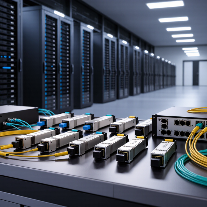
A 10G transceiver is a compact module that sends and receives network data at up to 10 gigabits per second. It converts electrical signals into optical signals, or keeps them electrical. This makes it a key link between switches, servers, storage systems, and routers. Fiber-based modules suit longer distances and electrically noisy areas. Copper-based modules can simplify short connections inside a rack. The correct choice depends on distance, cable type, connector design, and equipment compatibility.
Tips: Check the interface standard, transmission distance, wavelength, and operating temperature. Confirm whether the device supports single-mode or multimode fiber. Review power limits and digital monitoring features before installation. A module may fit physically but still fail because of coding or firmware restrictions. Test one unit with the actual switch before ordering many. Small checks prevent expensive downtime.
In practical deployments, distance is often underestimated. A 300-meter link can behave differently from a 30-meter rack connection. Connector cleanliness also matters, especially with high-density fiber panels.
I have seen specifications appear correct while the cable path introduced unexpected loss. That result is a useful reminder: published reach is not a guarantee in every installation. Leave room for maintenance, future bandwidth needs, and imperfect cable routing. A reliable 10G link is built from matched components, measured power levels, and careful records.
Choosing a 10G transceiver in 2026 starts with the equipment port, not the fiber cable. SFP+ remains the usual 10GbE form factor. It fits many switches, routers, and security appliances. However, a physically compatible cage does not guarantee operational compatibility. Check the device manual for supported speeds, coding, power limits, and digital monitoring.
Cisco’s Annual Internet Report estimated 29.3 billion connected devices worldwide by 2023. That scale makes reliable port matching increasingly important. For a 10G link, confirm whether the host expects SFP+, SFP28 operating at 10G, or a specific vendor-coded module. These options may share a similar shape, but their firmware behavior can differ. A mismatch may cause alarms, unstable links, or no link at all. The easy assumption is often wrong.
Port density also changes the decision. QSFP+ and QSFP28 ports usually serve higher-speed links, yet some systems support breakout cables. One QSFP28 port may split into four 10G lanes, but only when the switch and cable support that mode. IDC’s 2024 Ethernet Switch Tracker reported continued double-digit data-center switch revenue growth, increasing pressure on rack space and power budgets. Measure the cage clearance, airflow direction, and module temperature. Then verify the fiber type, wavelength, and reach. I have seen installations where the optics matched the speed but not the duplex polarity. That mistake is small. The downtime is not.
How to Choose the Right 10G Transceiver in 2026?
Selecting a 10G transceiver starts with the installed fiber, not the switch model. For short data-center links, multimode fiber is often practical. An SR transceiver commonly uses 850 nm light and supports about 300 meters over OM3 fiber. OM4 can extend that distance to around 400 meters. Measure the actual route, including patch panels.
For longer connections, choose single-mode fiber. An LR transceiver usually operates at 1310 nm and reaches approximately 10 kilometers. ER options may reach 40 kilometers, but they require careful loss-budget checks. Distance claims can mislead. Splices, dirty connectors, and tight bends reduce real performance. Leave engineering margin.
Wavelength also affects the link design. Standard duplex optics use two fibers, while BiDi optics send and receive through one fiber. BiDi pairs must use matching transmit and receive wavelengths. A small mismatch can stop the link completely. I have seen installations fail because the fiber type was correct, but the optical direction was wrong. Check connector polarity, module temperature ratings, and diagnostic readings before deployment. Testing every strand is slower, yet skipping it creates expensive troubleshooting later.
The chart compares typical maximum link distances for common 10G Ethernet optical interfaces. Multimode fiber is generally selected for short data-center links, while single-mode fiber is used for longer campus, metro, and telecom connections. Wavelength also affects fiber compatibility: 850 nm is common for multimode links, while 1310 nm and 1550 nm are used with single-mode fiber.
Choosing a 10G transceiver in 2026 starts with compatibility, not advertised speed. Check the switch’s port coding, firmware support, wavelength, fiber type, and diagnostics. A duplex LC plug can still fail if the module’s EEPROM profile is rejected. IEEE 802.3-2022 lists 10GBASE-SR reach up to 300 meters on OM3 and 400 meters on OM4. 10GBASE-LR reaches 10 kilometers over single-mode fiber. These figures require compliant loss budgets, clean connectors, and correct polarity. In real racks, patch panels often reduce the margin.
Compare measured latency, optical power, receiver sensitivity, and temperature range. For a 120-meter server room, SR usually avoids unnecessary optical cost. For a campus route, LR may be safer after checking splice loss and dispersion. Ask for test reports, not marketing claims. Validate DOM readings at cold start and after several hours. A module may pass a bench test yet flap under specific switch firmware. That is annoying, but real.
Power deserves equal weight. The IEA Electricity 2024 report estimates that data centers consumed about 460 TWh globally in 2022 and may exceed 1,000 TWh by 2026. The Uptime Institute’s 2024 Global Data Center Survey also identifies power availability as a major deployment constraint. Compare typical and maximum consumption, not only nominal watts. SFF-8472 diagnostics can reveal temperature and voltage behavior. I would not choose the lowest-power option blindly; lower draw can hide shorter reach or weaker diagnostics. A small pilot in the target switch remains the most reliable evidence.
| Transceiver Type | Typical Wavelength | Recommended Fiber or Cable | Typical Reach | Transmission Performance | Typical Maximum Power | Compatibility Requirements | Best-Fit Use Case | Important Limitations |
|---|---|---|---|---|---|---|---|---|
| 10GBASE-SR SFP+ | 850 nm multimode | OM3 or OM4 multimode fiber | Up to 300 m over OM3; up to 400 m over OM4 | 10.3125 Gb/s Ethernet; short-distance optical link; usually uses duplex LC connectors | Typically up to 1.0 W; many current modules operate below this level | Requires an SFP+ port supporting 10GbE and multimode optics. The host must accept the module's coding and operating temperature range. | Data-center switch-to-switch, switch-to-server, and top-of-rack connections | Not suitable for long single-mode fiber runs. OM1 and OM2 fiber provide shorter practical distances than OM3 or OM4. |
| 10GBASE-LR SFP+ | 1310 nm single-mode | OS1 or OS2 single-mode fiber | Up to 10 km | 10.3125 Gb/s Ethernet; low optical dispersion over standard access and campus distances | Typically up to 1.0 W; actual consumption depends on the optical design and temperature grade | Requires a compatible SFP+ host port and duplex single-mode fiber. Link budget, connector loss, and splice loss should be checked. | Campus networks, metropolitan links, and data-center interconnects up to 10 km | Higher cost than short-range multimode optics. Do not connect directly to multimode fiber without an appropriate optical conversion design. |
| 10GBASE-ER SFP+ | 1550 nm single-mode | OS2 single-mode fiber | Up to 30–40 km, depending on implementation and link budget | 10.3125 Gb/s Ethernet; extended-reach optical transmission with higher receiver sensitivity requirements | Typically up to 1.5 W | Verify host support, optical power limits, receiver overload protection, and the module's specified link budget. | Long campus, metropolitan, and regional connections where LR reach is insufficient | Exact reach is implementation-dependent. Excessive received power on short links may require an attenuator. |
| 10G Extended-Reach SFP+ | Usually 1550 nm single-mode | OS2 single-mode fiber | Up to 40–80 km, depending on the optical specification | 10GbE transmission over long distances; dispersion and power-budget engineering are critical | Often 1.5–2.0 W or higher | Must be supported by the host platform and matched to the required optical budget. Confirm management, temperature, and firmware compatibility. | Long-haul enterprise, utility, and metropolitan network links | Some extended-reach designs are vendor-specific rather than universally standardized. Validate interoperability before deployment. |
| 10GBASE-SR BiDi SFP+ | Two complementary wavelengths, commonly around 850 nm | Duplex multimode fiber using a matched transceiver pair | Commonly up to 100–300 m, depending on fiber grade and pair specification | 10.3125 Gb/s Ethernet over two optical directions using wavelength separation | Typically up to 1.0 W | Requires a matched A-side and B-side wavelength pair. Both modules must support the same speed, fiber type, and distance class. | Upgrading an existing fiber plant where one strand of a duplex pair is unavailable | A BiDi module cannot be paired with a standard duplex SR module. The two optical wavelengths must be complementary. |
| 10GBASE-LR BiDi SFP+ | Two complementary wavelengths, commonly in the 1270–1330 nm range | Single-mode fiber; usually one strand with LC or compatible simplex connectivity | Commonly up to 10 km | 10.3125 Gb/s Ethernet over one fiber strand using bidirectional wavelength division | Typically up to 1.0 W | Requires a matched wavelength pair, compatible SFP+ ports, and a single-mode optical path with an adequate link budget. | Fiber-constrained campus and metropolitan links where only one strand is available | Pairing modules with identical wavelengths will prevent communication. Connector polarity and optical direction must be verified. |
| Passive SFP+ Direct Attach Copper (DAC) | Not applicable; electrical copper cable | Twinaxial copper cable with integrated SFP+ connectors | Commonly 1–7 m; the exact limit depends on cable construction and host qualification | 10GbE electrical connection with very low latency and no optical conversion | Usually below 1.0 W per end | Both devices must support SFP+ DAC operation and the cable's electrical characteristics. EEPROM identification and host coding may affect acceptance. | Short rack connections between switches, servers, and storage systems | Heavy, less flexible than fiber, and unsuitable for long cable paths. Passive DAC length limits are stricter than active DAC limits. |
| Active SFP+ Direct Attach Copper (DAC) | Not applicable; electrical copper cable with signal conditioning | Shielded twinaxial copper cable with integrated electronics | Commonly 7–15 m | 10GbE electrical transmission with more reach than passive DAC and lower latency than optical alternatives | Typically up to 1.5 W per end | Requires host support for active DAC identification and electrical characteristics. Confirm the cable is qualified for both endpoints. | Rack-to-rack connections where fiber is unnecessary and moderate cable reach is required | Higher power and cost than passive DAC. Cable bend radius and airflow around dense cabling should be considered. |
| 10G SFP+ Active Optical Cable (AOC) | Usually 850 nm internally | Integrated multimode optical cable with fixed SFP+ connectors | Commonly 3–30 m; some qualified designs support longer distances | 10GbE optical transmission with low latency, small bend radius, and lighter weight than copper assemblies | Typically up to 1.5 W per end | Both endpoints must accept the cable's SFP+ identification and operating characteristics. The complete assembly is not field-repairable. | High-density racks, server-to-switch links, and short structured connections | Fixed connector spacing reduces flexibility. AOC assemblies cannot be separated into independent transceivers and patch cables. |
Choosing a 10G transceiver in 2026 requires more than matching connector types. Confirm the exact IEEE Ethernet standard, wavelength, reach, and fiber type. 10GBASE-SR suits short multimode links, while 10GBASE-LR supports longer single-mode connections. Check the transceiver’s MSA compliance and digital monitoring functions. Interoperability testing matters.
Reliability should be measured under real operating conditions. Review temperature ratings, optical power margins, error monitoring, and failure-history records. According to the Uptime Institute’s Global Data Center Survey 2023, 60% of reported outages cost at least 100,000 dollars. Small optical failures can become expensive incidents. Heat matters too. A crowded switch cabinet can reduce cooling efficiency and shorten component life. I have seen installations pass initial testing, then develop errors after months of dust and temperature changes.
Total deployment cost includes more than the module price. Add fiber cleaning, patch panels, testing labor, spare inventory, power use, and future replacement time. The Uptime Institute also reported that 15% of outages exceeded one million dollars, showing why operational risk deserves a clear budget. Use the Ethernet Alliance roadmap and current IEEE documentation when comparing migration paths. Calculate cost per usable link, not cost per transceiver. A cheaper module may require extra testing or earlier replacement. That assumption is easy to miss. Keep a small reserve of compatible units, but avoid excessive stock. Forecasts are never perfect.