Smart Heating Solutions
Global infrastructure is expanding, but project conditions remain uneven. Remote sites, changing pipe standards, and limited technical support challenge welding teams daily.
The International Energy Agency’s World Energy Investment 2024 report estimates global energy investment will exceed 3 trillion dollars. Much of that spending supports grids, pipelines, utilities, and industrial facilities. The World Bank also reports continuing infrastructure gaps across emerging markets. These trends create demand for reliable joining equipment, including the Fusion Pipe Welder.
Selection requires more than comparing heating plates or clamp sizes. A suitable machine must match pipe material, diameter range, wall thickness, voltage conditions, and site temperatures. Data logging matters when contractors must prove joint consistency across borders. Calibration records matter too. Small details can decide whether a weld passes inspection.
Welding engineer John C. Villafuerte offers a useful principle: “Control the variables, and the joint will tell the truth.” His observation fits global projects well. Operators need clear procedures, repeatable pressure control, accurate temperature readings, and accessible spare parts.
The 2024 Global Welding Equipment Market report from Research and Markets identifies automation, infrastructure renewal, and energy projects as major growth drivers. Yet market forecasts cannot replace field judgment. A powerful welder may still fail in dusty conditions or unstable power.
That is the uncomfortable part. No machine is perfect. Buyers should test equipment with actual pipe samples, not only brochure specifications. This guide examines capacity, portability, standards support, operator training, service coverage, and total ownership cost. The right Fusion Pipe Welder should perform reliably beside the trench, not merely inside a showroom.
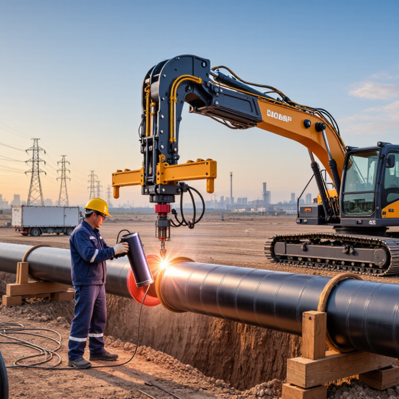
Choosing a fusion pipe welder starts with project scope, not machine appearance. Define the PE grade, SDR, diameter, pressure, and installation environment. Common polyethylene grades include PE80 and PE100, while diameters may range from 40 to 1,600 mm. ISO 4427 uses material strength, wall thickness, and safety coefficients to determine pressure capacity. For example, PE100 pipe with SDR11 has a theoretical working pressure near 16 bar at 20°C, before temperature and service adjustments. Confirm the actual rating with the pipe manufacturer’s technical data.
Machine capacity must match the largest joint. A 1,600 mm project needs high clamping force, stable hydraulic control, and accurate facing. Smaller 40 mm work may require different inserts or compact tooling. ISO 21307 and ASTM F2620 define controlled butt-fusion procedures, including heating, alignment, pressure, and cooling stages. PPI’s Handbook of Polyethylene Pipe also stresses clean surfaces, proper bead formation, and temperature control. These details matter in trenches, beside roads, and on exposed coastal sites.
Tips: Check wind, rain, dust, power supply, lifting access, and operator skill before selection. Use a data logger when quality records are required. For cold conditions, extend cooling time only under an approved procedure. I would not assume one machine fits every diameter. That assumption often fails. Pressure tables can also mislead when operating temperatures exceed 20°C. Review the project’s real fluid temperature, pressure surges, alignment tolerance, and emergency repair plan before ordering.
Choosing between butt fusion and electrofusion starts with the project’s joining conditions, not the machine’s advertised size. ISO 21307 and ASTM F2620 provide strong references for butt fusion procedures on polyethylene pipe and fittings. They address heating, alignment, changeover, pressure, and cooling. Check pipe diameter, wall thickness, SDR, resin type, and site temperature before selecting equipment. A powerful welder cannot correct poor preparation.
Butt fusion suits open work areas with stable pipe support and enough room for clamping. It can create efficient joints across larger pipe sections. Electrofusion is more practical near existing lines, tight trenches, repairs, or complex fittings. However, it demands careful scraping, cleaning, alignment, and controlled cooling. Use the applicable electrofusion procedure and fitting instructions. Do not copy butt-fusion settings. In field reviews, I have seen clean-looking joints fail after rushed alignment. A smooth bead is not proof of a reliable joint.
Tips:
Record pipe data before heating. Confirm machine calibration and temperature readings. Keep scraped surfaces dry and protected from dust. Watch the changeover time closely. Let the joint cool without movement. Recheck questionable joints instead of accepting them too quickly. This step is often skipped. That is a costly weakness.
How to Choose a Fusion Pipe Welder for Global Projects
DVS 2207-1 makes heat, pressure, and cooling control central to pipe-joint reliability. For polyethylene, heated-tool surfaces commonly operate near 210°C, with a ±10°C tolerance. However, material grade, wall thickness, pipe diameter, and ambient temperature can change the approved setting. Select equipment that records actual surface temperature, not only the programmed value.
Pressure control deserves equal attention. The welder should compensate for hydraulic drag, alignment resistance, and pipe dimensions. A stable gauge is useful, but digital logging provides stronger evidence during inspections. Cooling must remain controlled under pressure until the joint gains enough strength for handling. Premature movement can distort the bead. It happens.
The need is growing. FAO AQUASTAT reports that agriculture represents about 70% of global freshwater withdrawals, increasing demand for dependable irrigation networks. The UN World Water Development Report 2023 also emphasizes resilient water infrastructure and better operational management. For international projects, choose a machine with calibrated sensors, multilingual records, adaptable power input, and procedures aligned with DVS 2207-1. Confirm the calibration interval before purchase. I would also question impressive automation claims without traceable weld data. A neat weld is not automatically a qualified weld.
| Control Area | Specification Dimension | Recommended Project Data | Selection Requirement for the Welder | DVS 2207-1 Application Note |
|---|---|---|---|---|
| Applicable Process | Joint method | Heated-tool butt fusion of thermoplastic pipes and fittings | Use a machine designed for butt fusion, with controlled alignment, heating, joining, and cooling stages. | The procedure is intended for thermoplastic materials suitable for butt welding; the approved material procedure remains controlling. |
| Pipe Compatibility | Material and dimensions | Material grade, outside diameter, wall thickness, SDR, and fitting geometry must be entered before welding. | Select a machine whose clamping range covers the complete project diameter range and wall-thickness range without overloading the carriage. | Heat, pressure, and time values are dependent on the material and pipe dimensions; they are not universal fixed settings. |
| Heating Temperature | Heated-tool surface temperature | Typically 200–220 °C for PE-HD applications; use the approved material-specific welding procedure for PP, PVDF, or other polymers. | The heating plate should provide closed-loop temperature control, distributed heating, over-temperature protection, and a calibrated display or data output. | The selected setpoint must follow the applicable DVS material table and the pipe manufacturer’s qualified procedure. |
| Temperature Uniformity | Heating plate across the working area | Specify a documented temperature verification across the active heating surface before production. | Choose a plate with stable heat distribution, low thermal recovery time, and a calibration record traceable to the project quality system. | Uniform heating is necessary to avoid incomplete melting, local overheating, or asymmetric bead formation. |
| Bead-Up Pressure | Initial contact and bead formation | Normally limited to approximately 0.02 N/mm² or less, subject to the approved welding procedure. | The hydraulic system must permit low, stable pressure control and prevent accidental application of joining pressure during the initial heating stage. | Excessive initial pressure can force molten material away from the joint interface and reduce the effective fusion area. |
| Heat-Soak Pressure | Maintaining contact during heating | Maintain the low heating pressure specified by the approved procedure; do not use the full joining pressure. | Select a machine with a pressure-relief or controlled hold function that remains stable while the pipe ends are heated. | The heating phase must produce adequate melt layers without excessive displacement of the softened polymer. |
| Joining Pressure | Fusion pressure after heater removal | Common PE planning value: about 0.15 N/mm²; confirm the exact value for material, SDR, diameter, and procedure. | The machine must calculate or display the required hydraulic pressure from the selected fusion pressure and effective piston area. | Do not compare hydraulic gauge pressure directly with interface pressure; the conversion depends on machine geometry and piston area. |
| Pressure Calculation | Machine pressure versus interface pressure | Use the machine-specific relationship: hydraulic pressure = required joining force ÷ effective piston area. | Require a calibrated pressure gauge or transducer, verified piston-area data, pressure compensation for drag, and a documented pressure chart. | Pipe-wall friction and carriage drag must be considered when converting the specified fusion pressure into machine settings. |
| Changeover Control | Removing the heater and closing the joint | Keep the changeover interval as short as practicable and within the approved procedure’s maximum limit. | Choose a machine with rapid, unobstructed heater withdrawal, clear operator access, and an adjustable changeover timer. | Long or uncontrolled changeover time can cool the melt surface and reduce joint quality. |
| Heating Time | Time at the heated tool | Set by material and wall thickness; for PE, a commonly used planning reference is approximately 10 seconds per millimetre of wall thickness, subject to the approved procedure. | The controller should support recipe-based timing, countdown indication, operator confirmation, and data logging. | The project procedure takes precedence over generic planning estimates. |
| Cooling Under Pressure | Cooling time and pressure hold | Maintain the specified joining pressure throughout the required cooling period; cooling time must be selected from the approved material and wall-thickness procedure. | Require a locked pressure-hold cycle, cooling timer, low-pressure alarm, and protection against premature clamp release. | The joint should not be moved, stressed, or removed from the clamps before the specified cooling period has elapsed. |
| Ambient Conditions | Wind, rain, dust, and temperature | Use a weather shelter where wind, precipitation, direct solar heating, or contamination could affect the joint. | Select equipment compatible with outdoor power supplies and provide a wind shield, protected controls, and stable operating support. | Environmental conditions may alter heat transfer and cooling behavior; the procedure should define acceptable limits and corrective actions. |
| Alignment and Drag | Mismatch, ovality, and carriage resistance | Verify alignment, clean pipe ends, measure drag pressure, and include drag compensation in the pressure setting. | Choose rigid clamps, an adjustable carriage, a facing tool with sufficient torque, and a method for recording drag pressure. | Poor alignment or unaccounted drag can produce uneven bead geometry and an incorrect actual fusion pressure. |
| Data Recording | Traceability and quality records | Record joint ID, date, operator, material, diameter, wall thickness, temperature, pressure, heating time, changeover time, joining time, and cooling time. | For international projects, prefer automatic cycle recording, exportable files, calibration reminders, and multilingual operating instructions. | Recorded parameters support verification that each joint followed the approved welding procedure. |
| Calibration and Verification | Temperature, pressure, and timer accuracy | Complete pre-project and periodic checks using calibrated reference instruments and retain the certificates. | Specify accessible calibration points, replaceable sensors, pressure-gauge verification, and service support for the project region. | Control settings are only reliable when the measuring and control systems are verified and maintained. |
Choosing a fusion pipe welder for global projects starts with the generator, not the machine catalogue. Size matters. A 1600 mm joint needs far more energy than a 40 mm connection. Check heater output, hydraulic demand, control systems, and startup current together. Add capacity for cold mornings, long cables, and unstable site power. A generator running at its limit may cause voltage drops and uneven heating.
Cycle time also affects project cost. Larger pipes require longer heating, changeover, and cooling periods. Wall thickness, material grade, ambient temperature, and fusion pressure can change the schedule. Review verified cycle data for each diameter range. A machine rated for 40–1600 mm sounds flexible, but its clamping system must support that range safely. Modular inserts can help, although frequent changes may slow production.
Practical site checks often reveal hidden limits. Measure the generator under load, not only at idle. Confirm that the hydraulic unit maintains pressure during bead formation. Allow breathing room. I have seen crews select equipment by maximum diameter, then struggle with transport weight and connection space. That decision needs more reflection. Compare actual pipe sizes, daily joint targets, available power, and trained operators. Keep records of heating temperatures, pressure readings, and cooling times. These records support reliable quality checks across different countries and working conditions.
2026 How to Choose a Fusion Pipe Welder for Global Projects
Global projects need more than heat and pressure. Choose equipment aligned with the relevant ISO 12176 requirements, especially for butt-fusion or electrofusion work. ISO 12176-1 covers butt-fusion machines, while ISO 12176-2 addresses electrofusion equipment. Check the exact standard edition and project specification. A machine may meet one part but not another.
CE marking indicates conformity with applicable European requirements; it is not a universal quality certificate. UL marking may support acceptance in North American projects, but the marking type and electrical scope must match the installation. Grand View Research estimated the global welding equipment market at about USD 23.45 billion in 2023, with continued growth expected through 2030. More suppliers also means more documentation to verify. Do not trust a logo alone. Request declarations, test records, calibration evidence, and serial-number matching.
Tips: Require automatic recording of pipe size, material, fusion temperature, pressure, time, operator ID, and machine ID. Exportable reports should use secure timestamps and prevent silent edits. ISO 12176-4 can support traceability coding, but software compatibility remains uneven. Test one complete report before mobilization. On a remote site, weak connectivity can break cloud workflows. Local storage is safer, although it creates another backup task. I would also inspect calibration intervals and sensor replacement history. A compliant machine without usable records may still fail an audit.